Getting Softer
Written by Piers Cawley on , updated
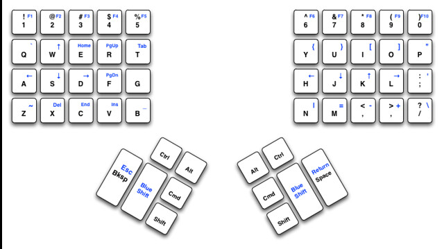
Welcome back. I realise that I left off without telling you how I’d chosen to wire the matrix up. I’m basing my layout on the Jesse’s “Blue Shift” layout: However, the Maltron has a slightly different layout and I’m less gung ho about getting rid of the extra little finger keys, especially the left hand control and the shifts. The layout I’m starting from looks a little like this: If you count that up, it’s 60 keys.
Welcome back. I realise that I left off without telling you how I’d chosen to wire the matrix up. I’m basing my layout on the Jesse’s “Blue Shift” layout:
However, the Maltron has a slightly different layout and I’m less gung ho about getting rid of the extra little finger keys, especially the left hand control and the shifts. The layout I’m starting from looks a little like this:
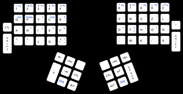
If you count that up, it’s 60 keys. There are 112 keys in the original Maltron layout arranged in 8 rows of 16 columns (which means that the total number of keys that could be accommodated in the matrix is 16 * 8 or 128. Because I was using only 60 keys, I could fit everything in an 8x8 matrix, which I wired up like this:
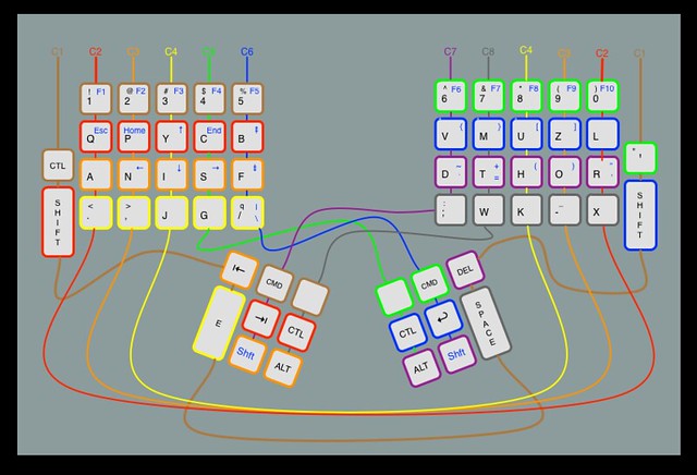
Once all the keys were wired up, I tacked ribbon cable in place to pick up signals, crimped terminations on the other end, plugged in the Teensy++ and went searching for firmware software.
Jesse had settled on the Humble Hacker Keyboard Firmware, but I found I couldn’t get on with it, and I ended up with the tmk firmware if only because it’s the first one I managed to get working and I found the documentation a wee bit more comprehensible. However, it was driving me up the wall for while because I simply couldn’t get it to recognise key presses as single keypresses. Keys would bounce, or wouldn’t register and I couldn’t work out what was going on until I read this tip on the Teensy website. It turns out that electronics is more subtle than I realised.
Pull up resistors (at last)
I’m a software guy. So I thought that the effective way of detecting a signal was to look for a positive voltage on your controller input pin. So zero volts implies that the input bit is false (zero in boolean logic). It’s a little bit more complicated than that though. It turns out that you get a clearer signal if you treat a pin being pulled to ground as true. To do this, we need some way of arranging for our input pin to be at 5V when the switch is open and, which (if you don’t know the trick) is more tricky, at 0V when the switch is closed and current is not flowing. Enter the pullup resistor. Consider the following schematic:
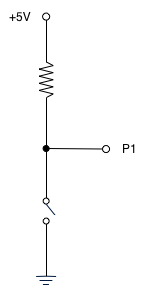
All we need to know to understand what’s going on now is Ohm’s Law. Ohm’s Law is almost laughably simple but once you’ve grasped it, understanding electronics gets much easier. The law states that the voltage (V) dropped across a load is equal to the product of the current flowing (I) in Amps and the resistance in Ohms (R).
So, when the switch is open (as in the diagram), we can see that the voltage between P0 and ground is equal to 5V - IR, but no current is flowing which makes IR equal to zero and so P0 is at 5V. So… what happens when the switch is closed?
We know that the voltage between the power rail and ground is 5V and we choose R so that the resistance of the switch might as well be zero. Which means that the voltage at P0 is 0V, or as near as makes no odds, so we have our two logic levels. When the switch is open, the input pin is at 5V, which we call false, and when it’s closed the pin is pulled down to ground (0V), which we call true.
So, if we recast our matrix driver so that, rather than applying a voltage to each column in turn and check the row pins to see if they’re high, we set up pull up resistors on the column pins and, set all our rows to 5V. Then, to scan the matrix, we set a row to ground and check which columns go to ground too and on to the next. The beauty of the Teensy is that we can do that without any extra hardware, we just set a couple of registers to appropriate values and we’re golden. Once I’d done this and rebuilt my debugging firmware suddenly the debugging output was making more sense. No missed keys. No strange repeats. No keys I hadn’t touched suddenly deciding they’d been pressed. Lovely.
There’s another possible problem with keyswitches called ‘bouncing’ that the firmware takes care of for me out of the box. In theory keyswitches are dead simple. You press the button and circuit goes from not conducting to conducting with no shilly shallying around. In practice… watching the voltage across even the best switch with a suitable oscilloscope is a lesson in the damnable imperfection of mechanical bits and pieces. The voltage is high. Then low. Then high. Then low. Then low. Then high. Then low and staying there. If you don’t take this into account in your driver you’re going to be registering far too many keypresses. Which is why any firmware worthy of the name has software debouncing (there are hardware debouncing solutions, but it’s much, much cheaper and more convenient to do the compensation) and the tmk firmware is no different. I’m sufficiently lazy that I’ve not really looked at how it works in any detail. Basically, if it detects a switch change it reads the same pin multiple times and, assuming the switch state is still changed at the end of that process, then it’s a real keyup or keydown event.
Faking it ’til you make it
The tmk firmware is substantially more competent than I’ve explored in any depth yet. I’m experimenting with what I want to do with the blue shift layer and distinguishing between taps, chording and other possibilities by setting up my ‘blue shift’ keys to send the ‘F12’ and F13’ keycodes and I’m using KeyRemap4Macbook to do most of my messing with stuff, but once I’ve worked out what I want, I expect to push as much as possible into the firmware so I don’t have to duplicate a bunch of work (and indeed find appropriate driver software) when I want to use the keyboard on a Linux or, in extremis, Windows box.
Traditions are there to be overthrown too
The keyboard on your computer is (unless you’re a weirdo like me and you’ve got a kinesis, maltron or some other alternative input device) is a living fossil. It takes the form it does because back when typewriters were invented, the mechanical constraints of needing to have typebars strike paper forced the designers to stagger the rows of keys. The keyboard layout was (allegedly) designed not to slow typists down, but to try and avoid getting keys tangled up with each other during typing by keeping common key combinations apart (I’m not entirely convinced that his is true, given that ’e’ is next to ‘r’ and ’t’ and ‘h’ are such near neighbours, but it’s pretty obvious that the qwerty layout isn’t really designed to minimise finger travel while touch typing (one wonders if they’d even thought of touch typing when they designed the thing). There’s no real reason to remain tied to this design. The Maltron case is designed so that there’s not much lateral movement of your fingers or wrist flexion while typing. Once you’ve learned the layout, it’s a delight to type with. But even with the radical case design and rejigged layout the Maltron is a surprisingly conservative design. The microcontroller I’m using to drive the keyboard is a pretty capable 8bit computer running at 16MHz, 8K RAM, 4K of EEPROM and 128K of flash memory to hold the program. Scanning an 8x8 matrix doesn’t come close to pushing it.
So, if we’re not tied to ‘one key one action’, what can we do?
Here’s what I’ve been experimenting with so far:
Distinguishing between tapping and press and then release. And between typing a key by itself and using it as a modifier. So at the moment I have:
If I tap (press and release quickly without pressing another key) the left blue shift, then pretend I actually tapped the tab key. If I press the key and, while holding it down, hit another key, send the ‘blue shift’ symbol associated with that key or just send L_ALT + the original keycode if there’s no blue shift symbol. The right blue shift works similarly but instead of sending tab on tap, we send RET. If I press either key hold it for a while and then release it, we don’t send anything.
The two keys on the far left (shift and control) send ESC when tapped.
I’ve also arranged things so that both ALT keys send R_ALT. I realise that might seem weird, but I’ve also configured my Emacs to treat R_ALT as a SUPER key which lets me bind actions to blue shifted keys. So when I’m in Emacs, all those keys without a blue symbol on them have more or less complicated actions associated with them. Others have used teensy based firmwares to have certain key combinations move the mouse pointer or trigger complex sequences of actions.
I’ve also got enough pins spare on the teensy that (and enough holes in the case) that I’m seriously considering using hot glue to mount a few RGB LEDs behind some of the holes in the middle of the case so that, If I end up cooking up more keyboard layers, I can indicate the keyboard (and Emacs perhaps?) state with blinkenlights. Because how can a project be complete if there aren’t blinkenlights?
Next steps
Where next? I’m not sure. I’m still experimenting with the possibilities that open up once you realise that just because we’ve always simulated a mechanical typewriter there’s no reason to keep doing it. Hardware doesn’t have to be dumb.
And then there’s the fact that a sixty key layout in a case designed to hold over a hundred keys looks scruffy. Until I started hacking my keyboard I’d tended to think that a desktop 3d printer was, for me at least, a solution looking for a problem. But now I’m trying to work out how to build a better keyboard case… Well, I think I’ve found my problem.